Decoding
Now we have corrected the residual CFO and also have corrected the channel gain, the next step is to map the FFT output to actual data bits. This is the reverse process of encoding a packet.
- demodulation: complex number to bits
- deinterleaving: shuffle the bits inside each OFDM symbol
- Convolution decoding: remove redundancy and correct potential bit errors
- Descramble.
Step 1 and 3 depend on the modulation and coding scheme, which can be obtained from the SIGNAL field. The SIGNAL field is encoded in the first OFDM symbol after the long preamble and is always BPSK modulated regardless of the actual modulation. Recall that in 802.11a/g, one OFDM symbol contains 48 data sub-carriers, which corresponds to 48 data bits in BPSK scheme. The SIGNAL field is also convolutional encoded at 1/2 rate so there are 24 actual data bits in the SIGNAL field.
Next, we first go through the decoding process and then explain the format of both legacy (802.11a/g) and the HT (802.11n) SIGNAL format.
Demodulation
- Module:
demodulate.v - Input:
rate (7), cons_i (16), cons_q (16) - Output:
bits (6)
This step maps the complex number in the FFT plane into bits. Fig. 19 shows the constellation encoding schemes for BPSK, QPSK, 16-QAM and 64-QAM. also supported in OpenOFDM.
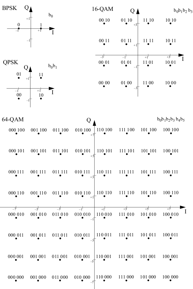
Fig. 19 BPSK, QPSK, 16-QAM and 64-QAM Constellation Bit Encoding
Inside each OFDM symbol, each sub-carrier is mapped into 1, 2, 4 or 6 bits depending on the modulation.
Deinterleaving
- Module:
deinterleave.v - Input:
rate (7), in_bits (6) - Output:
out_bits (2), erase (2)
Inside each OFDM symbol, the encoded bits are interleaved. To understand how the block interleaver works, first we need to define a few parameters. Here we only consider 802.11a/g and 802.11n single spatial stream mode.
| Modulation | Coding Rate | Bit-Rate | \(N_{BPSC}\) | \(N_{CBPS}\) | \(N_{DBPS}\) |
| BPSK | 1/2 | 6 | 1 | 48 | 24 |
| BPSK | 3/4 | 9 | 1 | 48 | 36 |
| QPSK | 1/2 | 12 | 2 | 96 | 48 |
| QPSK | 3/4 | 18 | 2 | 96 | 72 |
| 16-QAM | 1/2 | 24 | 4 | 192 | 96 |
| 16-QAM | 3/4 | 36 | 4 | 192 | 144 |
| 64-QAM | 2/3 | 48 | 6 | 288 | 192 |
| 64-QAM | 3/4 | 54 | 6 | 288 | 216 |
where:
- \(N_{BPSC}\): number of bits per sub-carrier
- \(N_{CBPS}\): number of coded bits per OFDM symbol
- \(N_{DBPS}\): number of data bits per OFDM symbol
Let \(s=max(N_{BPSC}/2,1)\) be the number of bits along the real (or imaginary) axis in the constellation plane. The interleaver is based on writing the data bits in rows and reading them out in columns.
| 802.11a/g | 802.11n 20MHz | |
| \(N_{COL}\) | 16 | 13 |
| \(N_{ROW}\) | \(3\times N_{BPSC}\) | \(4\times N_{BPSC}\) |
The interleaving process involves two permutations. Let \(k\) be the index of the bit index before the first permutation, \(i\) be the index after the first but before the second permutation, and \(j\) be the index after the second permutation.
The first permutation (\(k\rightarrow i\)) of interleaving ensures adjacent code bits are mapped to non-adjacent sub-carriers, and is defined as:
And the second permutation (\(i\rightarrow j\)) ensures that adjacent code bits are mapped alternatively to less or more significant bits in constellation point, and is defined as:
The deinterleaving process involves two permutations as well to reverse the two permutations in interleaving process.
First, to reverse the second permutation ((2)):
And to reverse the first permutation:
In OpenOFDM, the deinterleaving is performed using look up table. First, the bits in one OFDM symbol are stored in a two-port RAM. Then the bits are read according to the look up table.

Fig. 20 Deinterleave Look Up Table
As shown in Fig. 20, the raw bits of one OFDM symbol is first stored in the permutation buffer. The buffer entry is 6-bit wide to accommodate 64-QAM. For other modulations, only the lower \(N_{BPSC}\) bits are valid. The buffer has 48 (802.11a/g) or 52 (802.11n) rows depend on whether HT is used.
After all the bits inside one OFDM symbol are written to the permutation buffer, we first get the base address of the sub look up table for current modulation scheme. For 802.11a/g, the key is the rate bits inside the SIGNAL field. For 802.11n, the key is \(mcs+16\). The next step is to read the look up table to determine which bits to output next.
The lookup table entry is 22 bits wide, which contains:
null_a/null_b: whether the current bit is valid (for punctuation in Viterbi decoding next)addra/bita: the first bit to outputaddrb/bitb: the second bit to outputout_stb: output strobedone: end of sub-LUT for current modulation
Note that the deinterleave module output 2 bits at each clock cycle. The look up
table is generated by scripts/gen_deinter_lut.py.
For non 1/2 modulation rates, we need to compensate for the punctuation in the
deinterleaving step to make following Viterbi decoding easier. This is achieved
by inserting dummy bits (via the null_a/null_b bits) accordingly. The exact
punctuation pattern can be found in Figure 18-9 in 802.11-2012 std.
Viterbi Decoding
The transmitted bits are convolutional encoded which adds redundancy to the bits and help the receiver fix bit errors. The decoding can be performed using Viterbi algorithm. We utilize the Viterbi IP core provided by Xilinx. It is not free but you can obtain a evaluation license. The limitation of the evaluation license is that the core will stop working after certain time (several hours) after the FPGA is powered up.
The Viterbi core handles most of the heavy lifting and we only need to feed it with the de-punctured bits output from the deinterleave module.
For SIGNAL or HT-SIG fields, the decoding stops here. For data symbols, the last step is to descramble.
Descrambling
The scrambling step at the transmitter side is to avoid long consecutive sequences of 0s or 1s. The scrambling and descrambling process can be realized using the same logic.
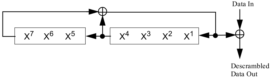
Fig. 21 Scrambler/Descrambler Logic
Suppose the current input bit is \(B_n\), the scrambled bit \(B^s_n\) and the internal state of the scrambler is updated as follows:
where \(X^i_n\) is the scrambler state before the nth input bit, \(n=0, 1, 2,\ldots\).
At the transmitter side, for each packet, the scrambler is initialized with pseudo random value. The very first 7 bits of the data bits is preset to zero before scrambling, so that the receiver can estimate the value using the scrambled bits.
Now let’s see how the receiver recovers the initial state of the transmitter’s scrambler. There are two ways to interpret this.
First, we can calculate the initial state. Since the first 7 un-scrambled bits (\(B_0\) to \(B_6\)) are all zeros, the scrambled bits can be obtained by:
From which we can reverse calculating the value of \(X\) as follows:
This interpretation does not lead to efficient Verilog implementation since we need to first buffer the first 7 bits, calculate the initial state and then descramble from the first 7 bits again.
The second interpretation is that: the first 7 scrambled bits are the state after scrambling the 7 bits. In other words, we have:
For instance, take a look at \(X_7^7\),
We also know that:
Therefore \(X_7^7 = B^s_0\). This way we directly get the state to descramble the next bit \(B^s_7\), resulting a very simple Verilog implementation.