SIGNAL and HT-SIG
The first OFDM symbol after long preamble is the SIGNAL field, which contains the modulation rate and length of the packet. These information are needed to determine how many OFDM symbols to decode and how to decode them.
Legacy SIGNAL
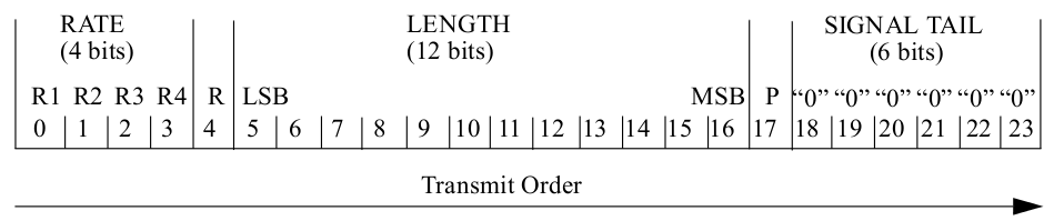
Fig. 22 SIGNAL field of 802.11a/g
For 802.11a/g, the SIGNAL field is 24-bits, which expands to 48 bits after 1/2 convolutional encoding and fits precisely into one OFDM symbol. Fig. 22 shows the format of SIGNAL.
In OpenOFDM, we check the following properties to make sure the SIGNAL field is decoded properly.
- Parity. Bit 17 is a even parity bit of the previous 17 bits.
- Reserved bit. Bit 4 is reserved, and should be 0.
- Tail bits. The last 6 bits should be all 0.
If any checking failed, we stop decoding immediately and wait for next power trigger.
HT-SIG
For backward compatibility, 802.11n shares the same preambles and SIGNAL field with 802.11a/g so that legacy stations can also decode the SIGNAL field and back-off accordingly (see NAV).
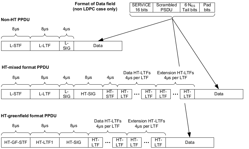
Fig. 23 PPDU Format of 802.11n
As shown in Fig. 23, there are actually three PPDU formats supported in 802.11n. The legacy mode is identical to 802.11a/g. The HT-mixed mode provides backward compatibility, and is mostly widely used. Finally, the HT-greenfield mode is pure 802.11n and does not have backward compatibility. OpenOFDM supports HT-mixed mode only.
In HT-mixed mode, the rate field in SIGNAL (or L-SIG) is always 6 Mbps, and the LENGTH is adjusted accordingly so that it reflects the actual packet air duration.
From receiver’s point of view, after decoding the SIGNAL field, if the rate is not 6 Mbps, then this is a 802.11a/g packet and we continue to decoding the DATA bits. However, if the rate is 6 Mpbs, then we need to first check if this is a 802.11n packet by detecting the HT-SIG field. This is achieved by examine the BPSK constellation points of the OFDM symbol after SIGNAL.
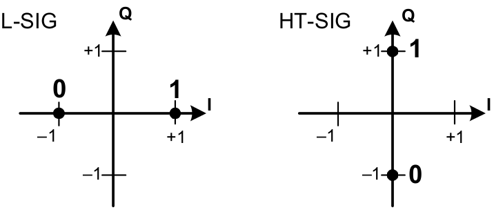
Fig. 24 Constellation Points of HT-SIG vs. SIGNAL
As shown in Fig. 24, HT-SIG is BPSK modulated using the Quadrature component instead of the In-phase component. Therefore, we check the number of samples in which the quadrature component is larger than in-phase, and claim a HT-SIG if enough such samples are detected (4 in OpenOFDM).
The HT-SIG field spans two OFDM symbols, and has 48 data bits (96 coded bits) in total. The constellation points are rotated 90 degrees clockwise before decoding.
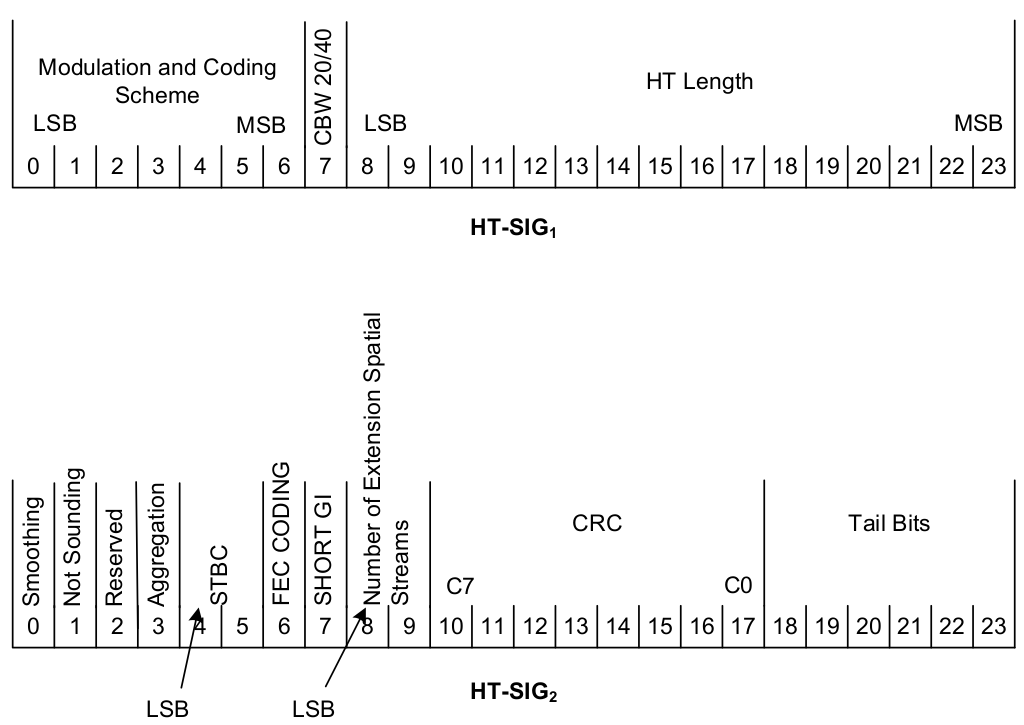
Fig. 25 HT-SIG Format
Fig. 25 shows the format of HT-SIG. The following fields are checked in OpenOFDM:
- MCS: only supports 0 - 7.
- CBW 20/40: channel bandwidth. OpenOFDM only supports 20 MHz channel (0).
- Reserved: must be 0.
- STBC: number of space time block code. OpenOFDM only supports 00 (no STBC).
- FEC coding: OpenOFDM only supports BCC (0).
- Short GI: whether short guard interval is used.
- Number of extension spatial streams: only 0 is supported.
- CRC: checksum of previous 34 bits.
- Tail bits: must all be 0.
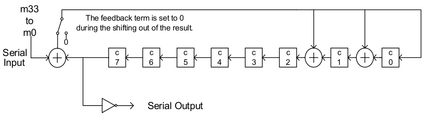
Fig. 26 CRC Calculation of HT-SIG
Fig. 26 shows the logic to calculate the CRC in HT-SIG. The shift registers \(C_0,\ldots,C_7\) are initialized with all ones. For each data bit \(m_0,\ldots,m_{33}\), the shift register is updated as:
The CRC is then \(\overline{C^{34}_7},\ldots,\overline{C^{34}_0}\). Note the bits are inverted.
The next OFDM symbol after HT-SIG is HT short preamble, which is skipped in
OpenOFDM. The following OFDM symbol contains HT long training sequence, which
replaces the legacy channel gain inside equalizer.v module. The rest
decoding logic is similar to 802.11a/g, except the number of data sub-carriers
is adjusted from 48 to 52.